

CHEMISTRY AND SURFACE ANALYSIS
Discover more about the services
CHEMISTRY AND SURFACE ANALYSIS
The activities of the chemical lab
The activities of the chemical lab are focused on the quality and quantity analysis of chemical substances to check the compliance with current regulations or the requirements of the examined materials.
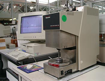
As for example the Fourier Transform Infra-Red Spectroscopy (FT-IR) provides with structural information on the analysed material through the interaction between an infra-red radiation and the material itself. This test is suitable to define the quality and the semi-quantity of the organic compounds.
MAIN PERFORMED TESTS
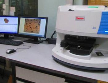
The metallographic tests.
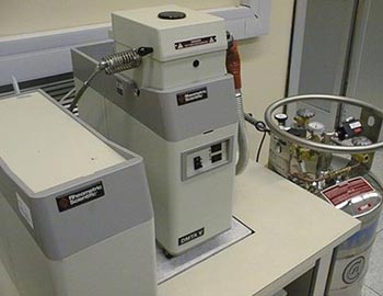
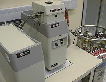
FT-IR (Fourier Transform Infra-Red Spectroscopy)
The Fourier Transform Infra-Red Spectroscopy (FT-IR) provides structural information about the analysed material thanks to the interaction of an infra-red x-ray with the material. This test is suitable for the quality and quantity analysis of organic compounds. The FT-IR analysis allows to identify the functional groups inside the molecules and the characterisation is performed comparing the spectra of the databases or by attributing every resulting peak to the vibration of a specific functional group. A limit of the instrument is represented by the fact that in case of analysis of natural organic substances, it allows only the distinction of the compound classes but not the one of the single substances (for example it identifies if a substance belongs to the oil category, but it doesn’t allow to identify which specific substance is).
Test method: ASTM E1252 (Standard Practice for General Techniques for Obtaining Infrared Spectra for Qualitative Analysis)
TIC – Total Ionic Contamination
The Ionic Cleanliness test is used to measure the conductivity/resistivity of a solution obtained by the sample treatment. The performed measurement can be related to the quantities of the ionic material on it; the resistivity of the solution decreases when the ionic contamination level increases. Usually, the ionic contaminators are flux residues or harmful materials which derive from the productive process, and they can downgrade the reliability of the electronic components and the assemblies because they contribute to the leaked current among the circuits by easing the dendritic growth and by increasing the corrosion risk.
Test method: IPC TM 650 2.3.25.1 (Ionic Cleanliness Testing of Bare PCBs) – This test is used to determine the total extractable ionic content from printed circuits (PCBs) to control the process.
Test method: IPC TM 650 2.3.25D (Detection and Measurement of Ionizable Surface Contaminants by Resistivity of Solvent Extract (ROSE)) – This test is used as process control instrument, and it can be used both in printed circuits and assemblies.
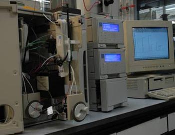
IC – Ion Chromatography
The Ion Chromatography (IC) is an analytical technique which divides ions and polar molecules depending on their charge. Every species interacts in a different way with the stationary phase (a column full of resin), and they have different retention times. This feature allows to quantify them individually after being separated. The test procedure is designed to measure the ionic contamination level extractable from the surface of printed circuits and assemblies, soldering fluxes, electrical components, etc.
Test method: IPC TM 650 2.3.28 (Ionic Analysis of Circuit Boards, Ion Chromatography Method), IPC TM 650 2.3.28.1 (Halide Content of Soldering Fluxes and Pastes), IPC TM 650 2.3.28.2 (Bare Printed Board Cleanliness by Ion Chromatography)
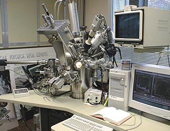
Inductively Coupled Plasma – Optical Emission Spectrometry
The Optical Emission Spectrometry (OES) is an analytical technique which allows to identify the traces of metal and uses the Inductively Coupled Plasma (ICP) to separate the sample into atoms and ions, that opportunely excited, release an electromagnetic radiation of different wavelength according to each element.
This test allows to determine the basic quality and quantity composition of the analysed sample.
Our chemical lab is also able to determine the carbon and sulphur concentration into metal alloys through a carbon and sulphur analyser (LECO). The application field of this analysis includes metals like steel, iron, copper, alloys, etc.
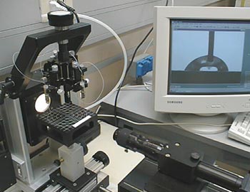
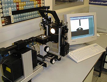
Determining the Contact Angle
The contact angle is a thermodynamic quantity which represents a measurement of wettability. This test measures the angle a drop of a liquid creates on the surface of a solid. The size of the contact angle between the liquid and the solid depends on the interaction between the substances and the contact surface. Lesser the interaction, greater the contact angle and it will be more difficult to wet the solid, which will have a lesser adhesion to foreign bodies. From the contact angle determination, it is possible to define some features of the surface like, for example, the surface energy.
Test method: ASTM D7490 Standard Test Method for Measurement of the Surface Tension of Solid Coatings, Substrates and Pigments using Contact Angle Measurements
Test method: ASTM D7334 Standard Practice for Surface Wettability of Coatings, Substrates and Pigments by Advancing Contact Angle Measurement
Glass Transition Temperature (Tg)
The Glass Transition Temperature is usually indicated with the symbol Tg, and it represents the temperature range at which an amorphous material moves from a hard, glassy condition to a more flexible, rubbery condition. This phenomenon is the so-called structural relaxation.
It is possible to define the Glass Transition Temperature by using different instruments:
– TM 2.4.24C Glass Transition Temperature and Z-Axis Thermal Expansion by TMA
– TM 2.4.25C Glass Transition Temperature and Cure Factor by DSC
– TM 2.4.24.2 Glass Transition Temperature of Organic Films – DMA Method
Coefficient of Thermal Expansion (CTE) with TMA
The Coefficient of Thermal Expansion describes how the size of an object can change in relation to a temperature variation. Usually, the substances expand themselves when their temperature changes and the relative expansion or reduction can occur in all the directions (isotropic material)
Test method: IPC TM650 2.4.24 (Glass Transition Temperature and Z-Axis Thermal Expansion by TMA)
Time to Delamination (with TMA)
The Time to Delamination is a measurement used to evaluate the basic material performance: it provides with an information about the time the resin and the copper require to separate or delaminate themselves. This test uses the TMS instrument to bring a sample (laminated or a printed circuit) at a specific temperature, and it measures the necessary time for the delamination.
Test method: IPC TM 650 2.4.24.1 (Time to Delamination (TMA Method))
Thermogravimetric Analysis with TGA
The Thermogravimetric Analysis measures the variation of the sample mass subjected to a heating with a controlled growth of the temperature. The result of the analysis includes a thermogram which indicates temperature/time on the x-axis and the absolute change or sample mass percentage on the ordinates (Thermal Decomposition Curve). This analytical technique is useful to evaluate the decomposition and oxidation processes.
Test method: IPC TM 650 2.4.24.6 (Decomposition Temperature (Td) of Laminate Material Using TGA)
Melting Point with DSC
The Differential Scanning Calorimetry (DSC) is a method that, considering the temperature, measures the difference between the thermal fluxes in a sample substance and into a reference, both subjected to a controlled temperature variation. This technique provides with information about the quantity of energy absorbed or released by the sample when it is warmed or cooled.
The common Melting Point of a material is identified with the temperature at which it changes its condition from solid to liquid. During this process, all the energy added to a substance is consumed as heat of fusion and the temperature remains constant. The analysis of Melting Point allows to obtain a first impression about the purity of a substance because some impurities change the fusion range.
Solder Pastes Analysis
The solder pastes are suspensions of stable and homogeneous particles of the soldering powder immersed into a liquid flux. By changing the size, the distribution, and the shape of the soldering particles, it is possible to control the rheology and the performances of the pastes.
1. Solder Ball Test – This test is performed to determine the solder paste re-flow properties during the re-fusion process.
Ref. Standard IPC TM 650 2.4.43 (Solder Paste – Solder Ball Test)
2. Slump Test – This test defines the vertical and horizontal slump of the solder pastes.
Ref. Standard IPC TM 650 2.4.35 (Solder Paste – Slump Test)
3. Wetting Test – The wetting test defines the ability of a solder paste to wet an oxidised copper surface and allows to examine, from the quality point of view, the spatter quantity of the solder paste during the re-fusion process.
Ref. Standard IPC TM 650 2.4.45 (Solder Paste – Wetting Test)
Determining Water Absorption
The water absorption test is performed to determine the quantity of absorbed liquid in specific environmental conditions. This analysis is affected by factors like the type of material, the additives used, the temperature and duration of the test. The results show the possible performances of the materials into water or in humid environments.
Test method: IPC TM 650 2.6.2.1 (Water Absorption, Metal Clad Plastic Laminates) – Determining of the absorbed water quantity by plastic laminates immersed into distilled water for 24 hours.
Flammability Test
The flammability is the capacity of a material to burn or explode by causing fires or combustion. The level of difficulty necessary to provoke the combustion of a substance is determined by the flammability test.
Ref. Standard: UL94 (The Standard for Flammability of Plastic Materials for Parts in Devices and Appliances) – Applicable to plastic material, it can determine the materials’ ability to propagate or put out a flame after having lighted it.
Copper mirror test
This test allows to detect the active substances inside the fluxes. The solder paste or the flux are placed on a substrate covered with a light copper layer. The presence (or not) of active substances will cause the removal of the copper layer on the substrate by allowing to understand the corrosive behaviour of the flux.
Test method: IPC TM 650 2.3.32 (Flux Induced Corrosion (Copper Mirror Method)), IPC J-STD-004 (Requirements for Soldering Fluxes)
Corrosion Test
The corrosion tests are essential to understand how the materials behave in severe or ongoing use conditions, and they can guarantee the achievement of the complete life cycle. This test eases the prediction, the planning, and the mitigation of the negative effects the corrosion can have on the materials on which they can be used.
Porosity Test
GEST Labs can test samples and materials to evaluate their porosity features and to characterise the empty spaces inside of them.
Test method: IPC TM 650 2.3.24 (Porosity of Gold Plating), Standard IPC 4552 (Specification for Electroless Nickel/Immersion Gold (ENIG) Plating for Printed Circuit Boards)
