

METALLOGRAPHY
Discover more about the services
METALLOGRAPHIC ANALYSIS
The science able to observe the inner structure of a material
The metallographic analysis is needed to understand the chemical, physical, mechanical, and technological features of metal materials, to evaluate the working conditions influence on the behaviour of the materials, to check the reaction of a material to the specific requests, and to identify possible anomalies and the relative causes.
The metallography is a science which observes the inner structure of a material by studying the crystal morphology. The details obtained by the metallographic analysis allow to check the condition of the material.
MAIN PERFORMED TESTS
The metallographic tests.
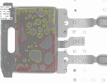
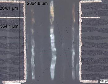
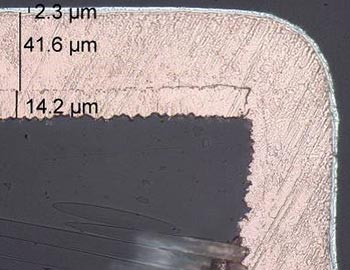
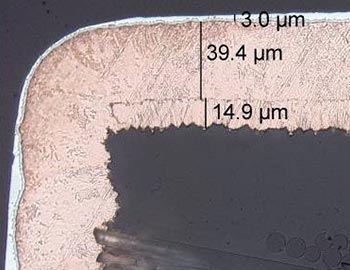
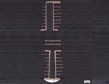
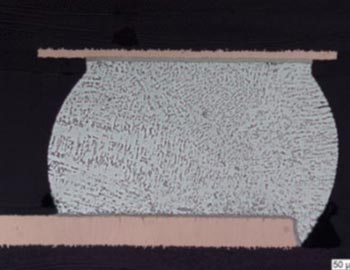
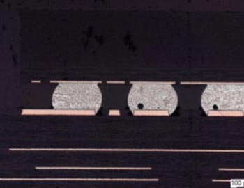
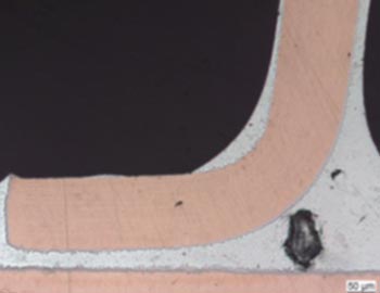
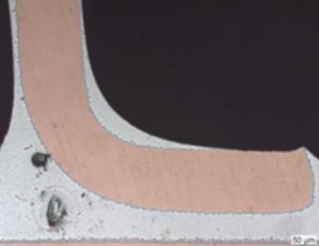
Metallographic microsections
Metallographic microsections
The cross section metallographic analysis is a destructive analysis which allows to check the right construction of the printed board by verifying the copper thickness in the inner layers and on the surface, the right application of solder mask, the metallisation of the inner holes, and the quality of the circuit boring.
The sample is sectioned and integrated into a specific resin; then by further mechanical processing, and the lapping of the to-be-analysed surface, it is observed through the optical microscopy.
Test method: IPC TM 650 2.1.1 (Micro sectioning, Manual method)
Analysis with optical microscope
The optical microscopy is a method of investigation essential for the structure analysis of the materials. This technique is effective for the study of the anomalies due to thermal treatment, for the evaluation of the inclusions, for identifying the breaks, and for the evaluation of the soldering and the coatings.
Technical regulations: IPC A-600 (Acceptability of Printed Boards), IPC A-610 (Acceptability of Electronic Assemblies), IPC 6012 (Qualification and Performance Specification for Rigid Printed Boards)
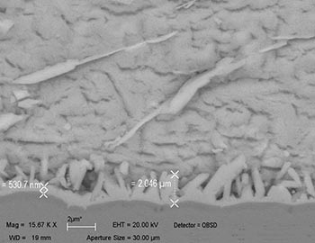
SEM (Scanning Electron Microscope) – EDX (Energy Dispersive X-Ray) Spectroscopy
The Scanning Electronic Microscope indicated as SEM is a type of microscope which allows a morphological investigation at high magnifications.
With the word EDX (Energy Dispersive X-ray Analysis) Spectrophotometry we indicate an instrumental analytical method whose work is based on the interaction between a primary focused electron beam which beats the sample and the electrons of the atom that constitute the sample itself.
The combined use of the two techniques allows the morphological characterisation (SEM) and the compositional one (EDX), and it provides with an instrument for the understanding of the composition of material structure.
Solderability Test
The Soldering Test on printed boards is performed on the base of IPC J-STD-003 Standard which describes the procedures and the methods to define the acceptability criteria of the wettability of the superficial finishing of the sheets.
Through this method it is possible to evaluate the weldability of:
– Superficial conductors;
– Fixing points;
– Plated-through holes (PTHs) of printed boards.
The Soldering Test of components is performed on the base of IPC J-STD-002 Standard which sets the testing methods, defines the defects and the acceptability criteria for the evaluation of the weldability of terminals and flexible cables. This test is necessary to check if the weldability of components terminals (lead) follows the requirements requested by the standard.
Test method: IPC J-STD-002 (Solderability Tests for Component Leads, Terminations, Lugs, Terminals, and Wires), IPC J-STD-003 (Solderability Test for Printed Boards)
Peel Strenght Test
The Peel Strength Test is generally used to measure the peel strength of a material, usually of an adhesive.
Through this test is possible to determine the comparative peeling features or breakout force of adhesive bonds tested on samples of specific sizes and in defined conditions of pre-treatment, temperature, and speed of the testing machine.
Test method: IPC TM 650 2.4.8C (Peel Strength of Metallic Clad Laminates)
Solder Float Test
This test is performed on PTH (Plated-Through-Holes) with the aim of determining if the PTH can support the thermodynamic effects of the extreme heat to which they can be exposed during the assembling, re-working, or restoration phases.
Test method: IPC TM-650 2.6.8 (Thermal Stress, Plated-Through Holes)
Dye&Pry Test
The Dye&Pry analysis technique is a destructive test used when it is impossible to solve a problem with the optical inspection (for example in case of too small defects).
This technique is based on the use of a liquid colourant which soaks into the microfractures existing on the soldering. When the colourant is dried, the electronic components (BGA, condensers, resistances, etc.) are removed from PCB and the soldering are inspected: the presence of the colourant reveals the problematic areas at the level of connections of all the interfaces.
Test method: Internal Method
X-Ray (2-D and 3-D defects analysis)
The X-Ray analysis of electronic sheets is a non-destructive technique which allows to identify and evaluate possible failures and/or defects at the level of open, voids, solder ball, and soldering breakouts. Furthermore, this test allows to check the correct soldering of components and to identify possible soldering voids.
The X-Ray analysis allows to find factors which could not be noticed with a simple visual inspection. The evaluation can be performed both through 2-D oriented presentations and 3-D volumetric views.
Technical regulations: IPC A-610 (Acceptability of Electronic Assemblies), IPC 7095 (Design and Assembly Process Implementation for BGAs).
